Gathering Light
Designing and Laser Cutting
Limitations of the Glowforge
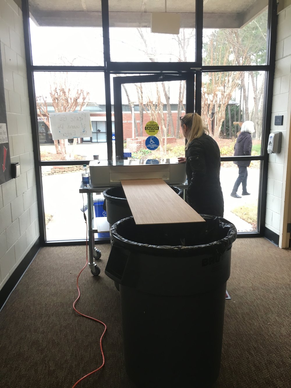
Designing the layout of panels and pixels for this project required more problem solving and working within limitations than my previous projects. The Glowforge has a cutting area of approximately 19.5” across by 11” deep, with a passthrough slot that allows you to use materials that are infinitely deep. The material has to be manually fed through the slot and aligned if cutting shapes larger than the cutting area.
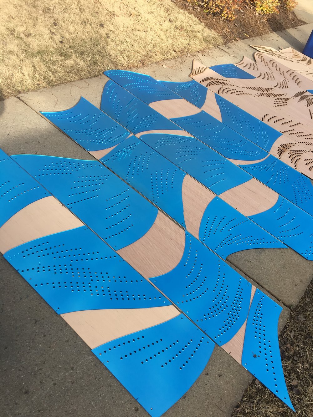
Alignment was not always accurate, so for this large project I decided that the horizontal sides of the material should be cut with a table saw and just the vertical cuts and holes would be laser cut. Based on the 48”x96” standard acrylic sheet size, the least wasteful option seemed to be creating panels that were 16” wide (ended up being 15-⅞” to account for blade width)
Designing in Processing
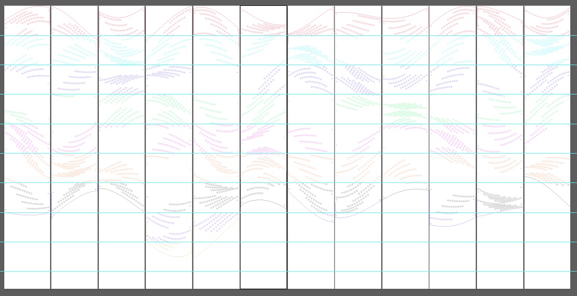
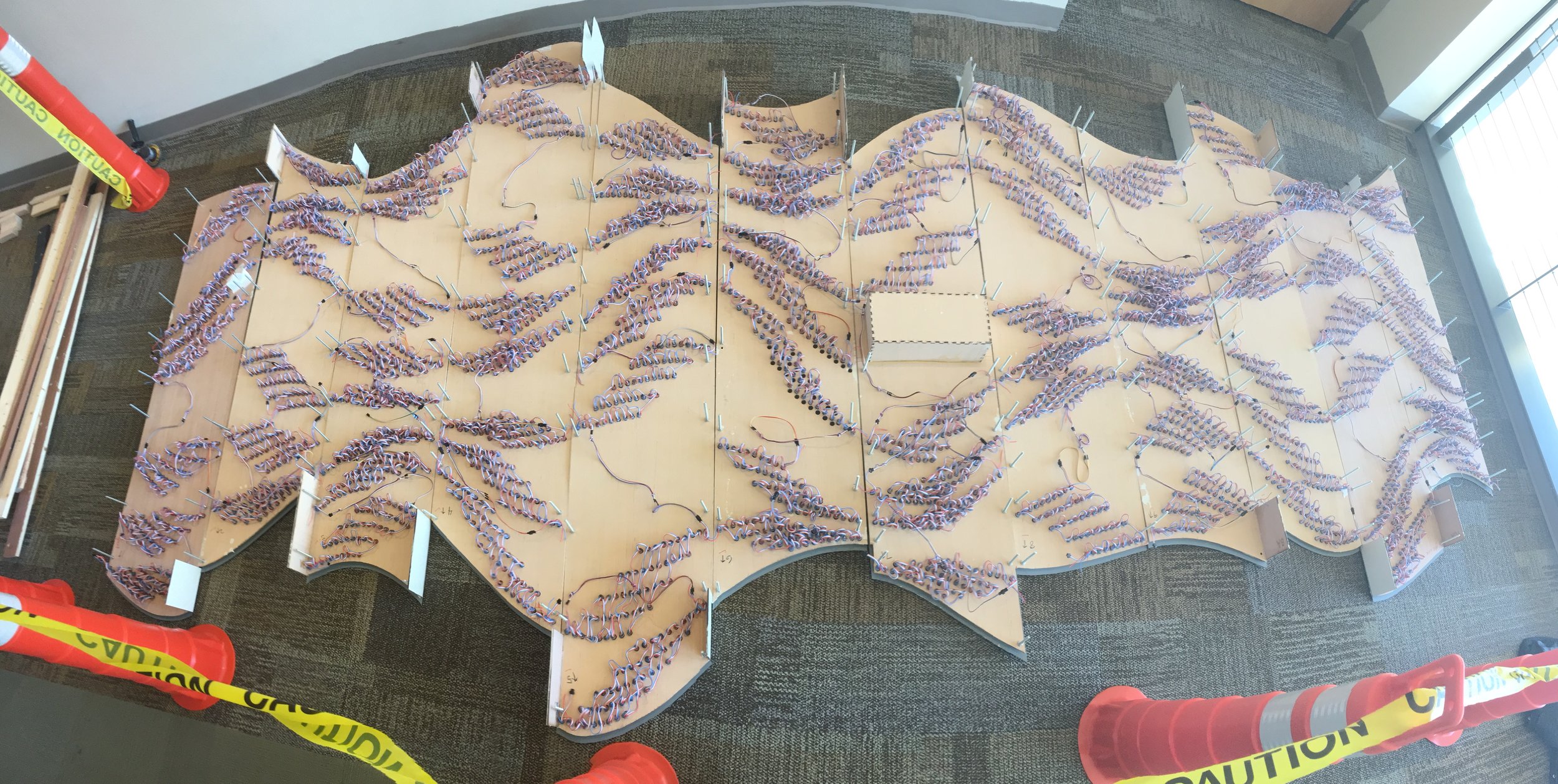
The arrangement started out as a blank 960x480 canvas in Processing, 5 pixels per inch for the 192”x16” composition, drawing vertical lines every 80 pixels to show the 16” panel separations. I used several embedded for loops to procedurally calculate x and y positions and then draw a 3x3 pixel ellipse to mark where each ½” LED would be placed. I created a variable “led” and incremented it by one after each ellipse was drawn to be able to keep track of how many LEDs were used.
Given the short amount of time for the project, I planned the arrangement in clusters of 50 LEDs (the number of LEDs per strip) so we did not have to spend hours cutting custom lengths and soldering on new connections.
Converting to Vectors
I’ve previously been dumb and exported images that are scaled up 10x and Image Traced in Illustrator and then converted the almost perfect paths to circles, but before writing this I just tried the PDF export library and this works 100x better. (Laughing at that one time in 2017 spent 8 hours manually drawing circles in Illustrator) Once the file is in Illustrator, it’s just a matter of resizing to the actual size, making sure the holes are the appropriate size, and adding additional holes for the hardware that connects everything together.
Prepping these files for Glowforge
The files need to be saved as an .SVG and the Glowforge software creates layers based on different color paths. We’ve had issues using Black lines, so it’s best to avoid them. Each layer can be set to Cut, Engrave, or Ignore.
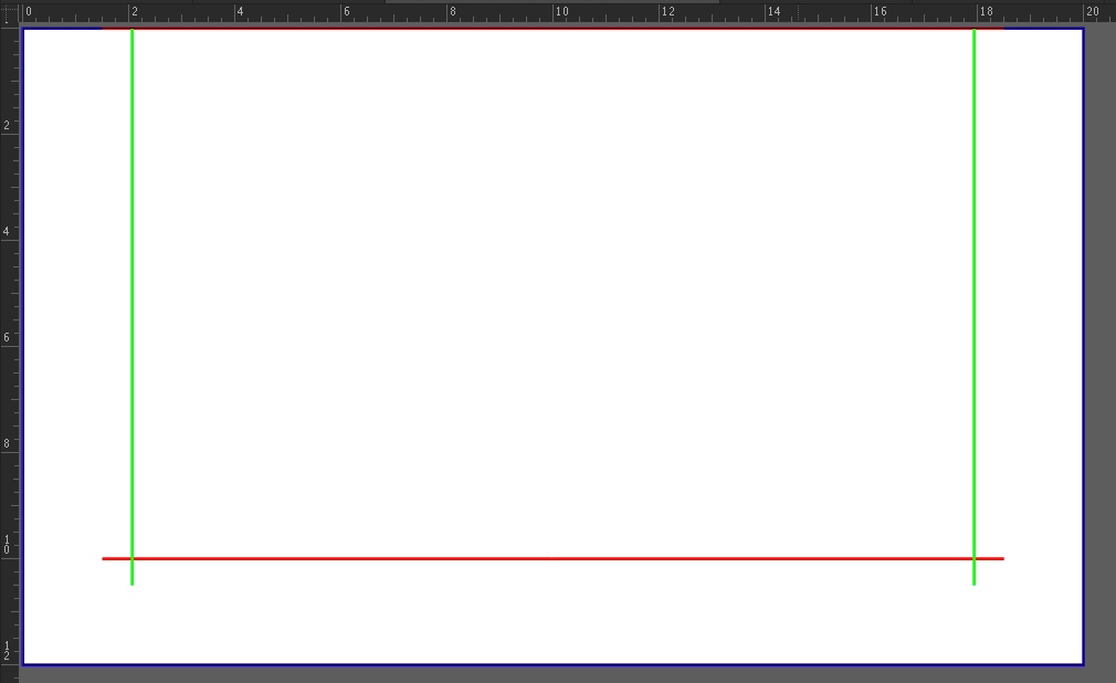
To avoid issues with files not coming in at the same place, I prepped all of our files to be enclosed in a 20”x12” rectangle the same size as the work area, so the file is always placed in the center. This rectangle is then set to be ignored.
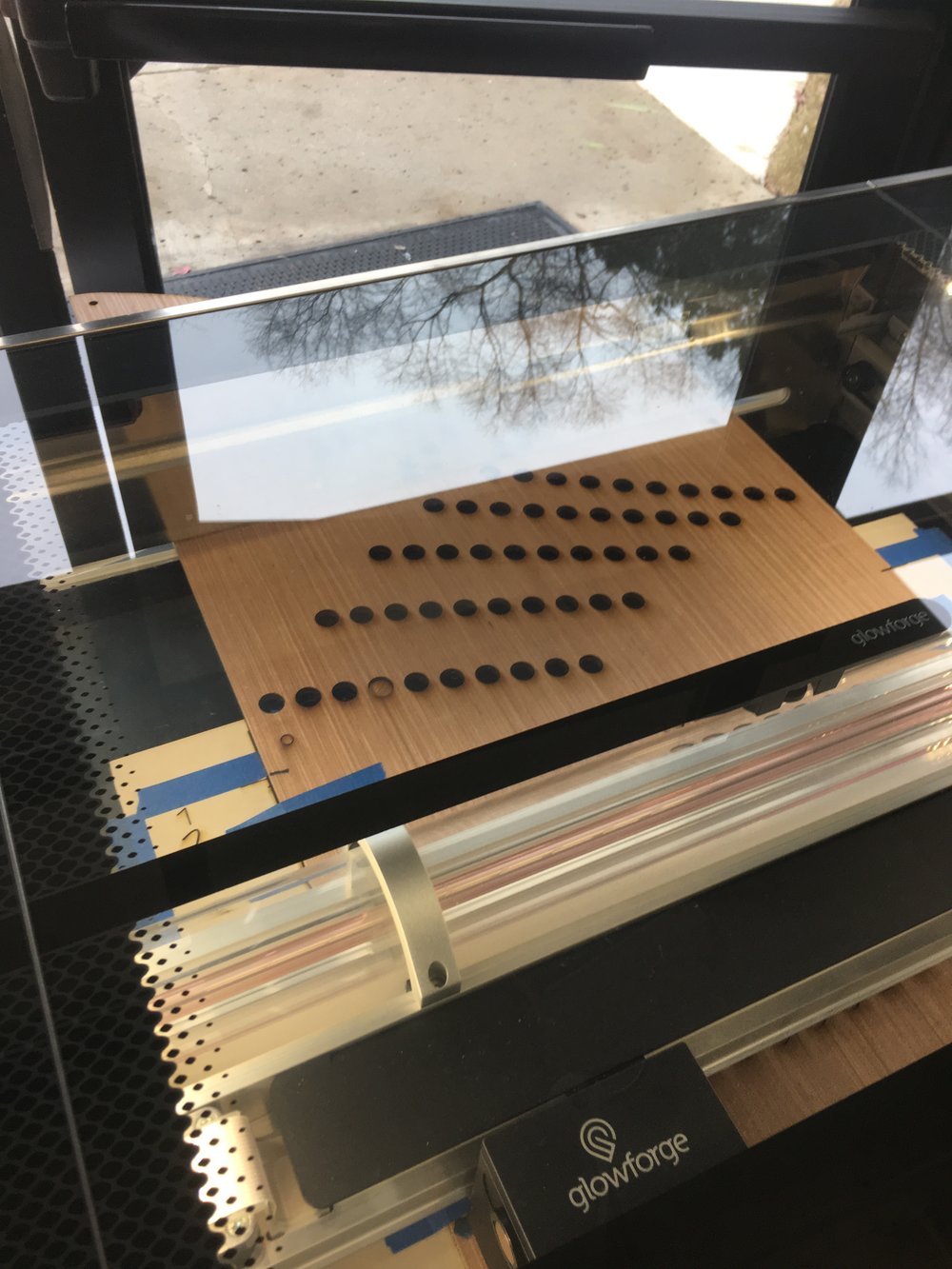
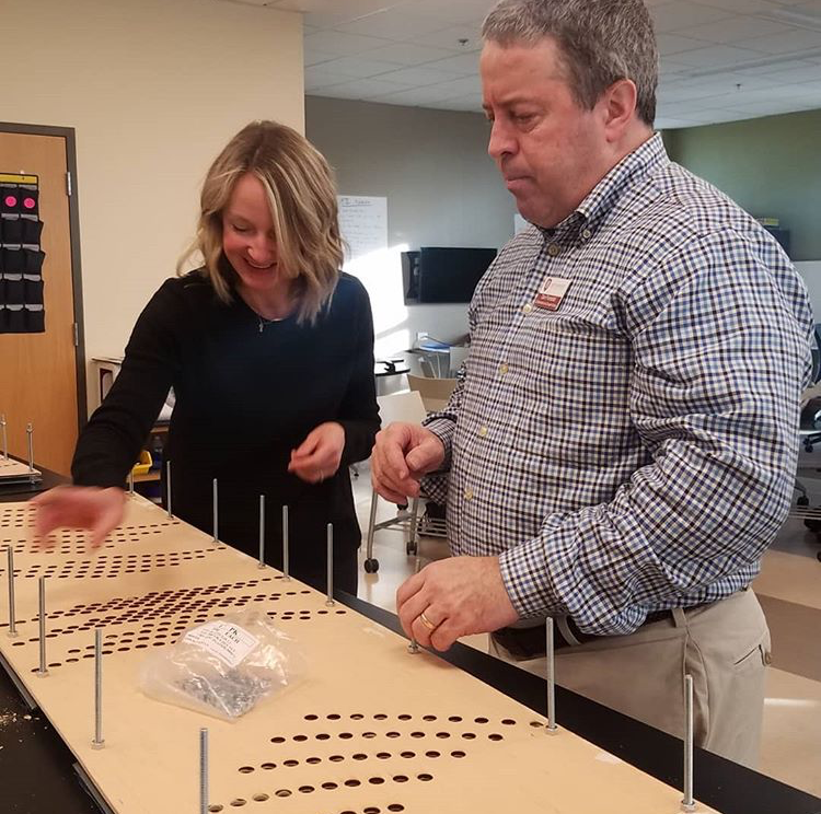
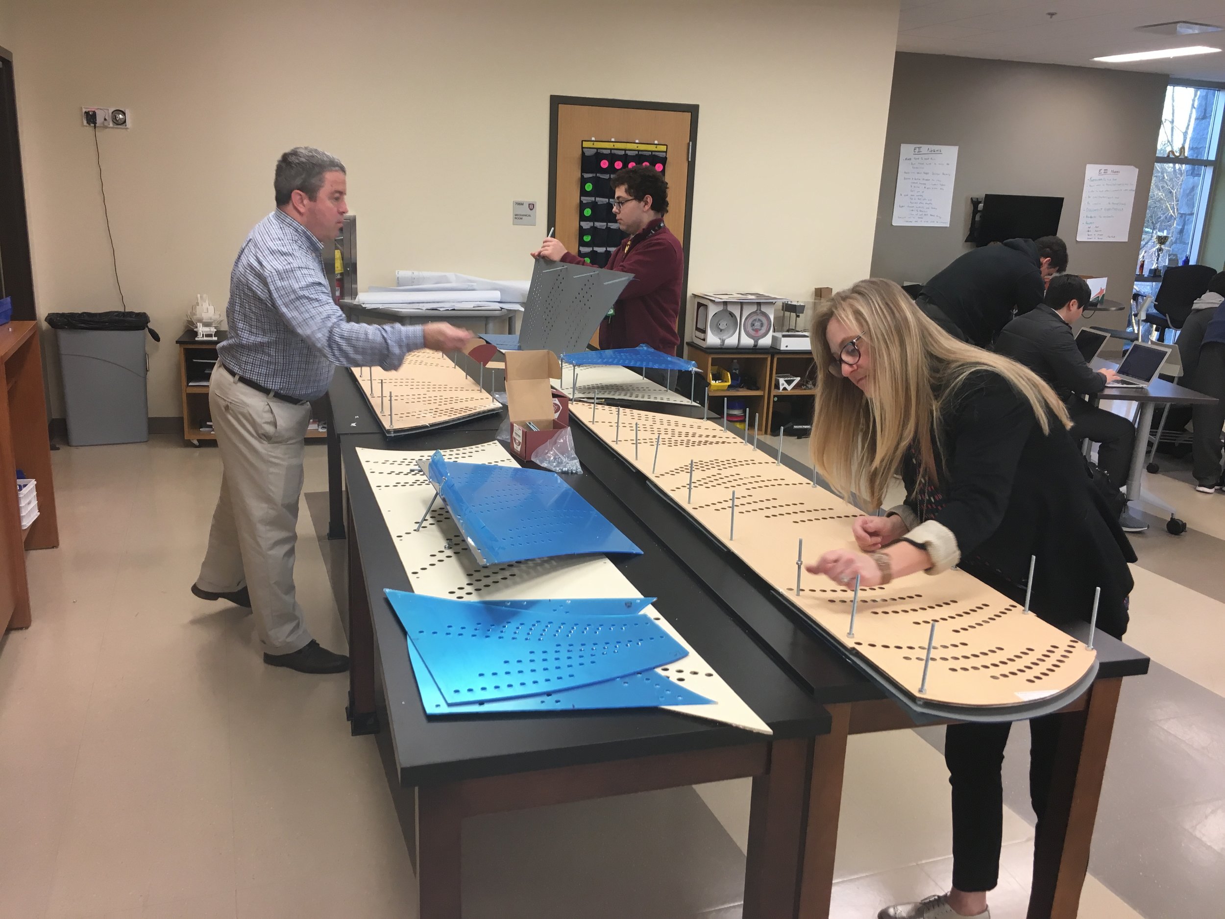
We cut a guide (see photo below) with a 15-⅞” window for our material, and engraved a line at the top of the work area and 10” below. To keep our cuts aligned for the panels, we placed the top of the material at the top line and marked it at the bottom line. After the section was cut, we moved the bottom mark up to the top line and repeated the process.
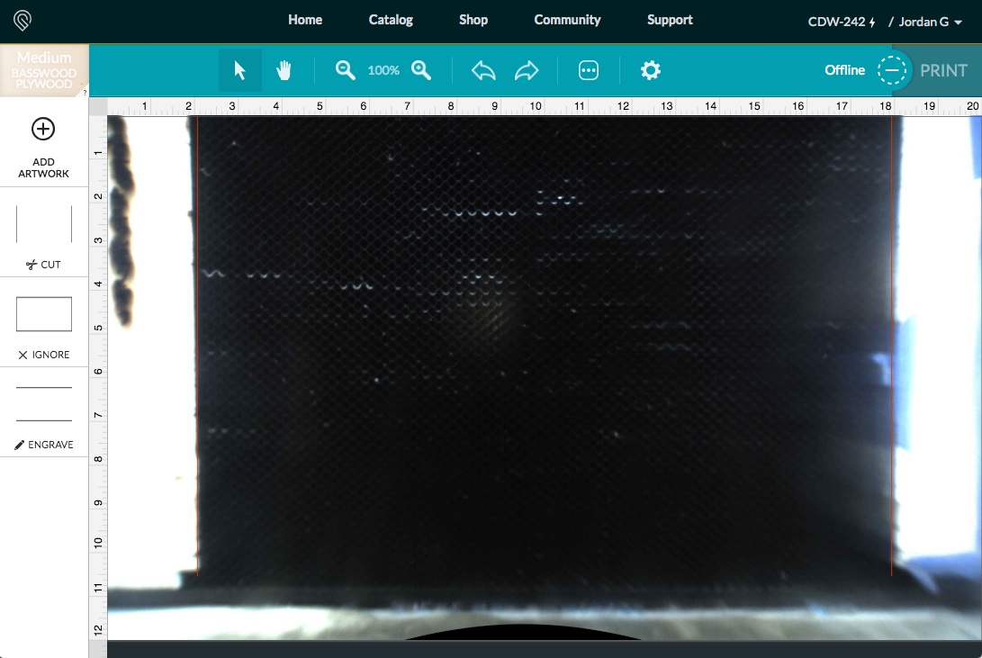
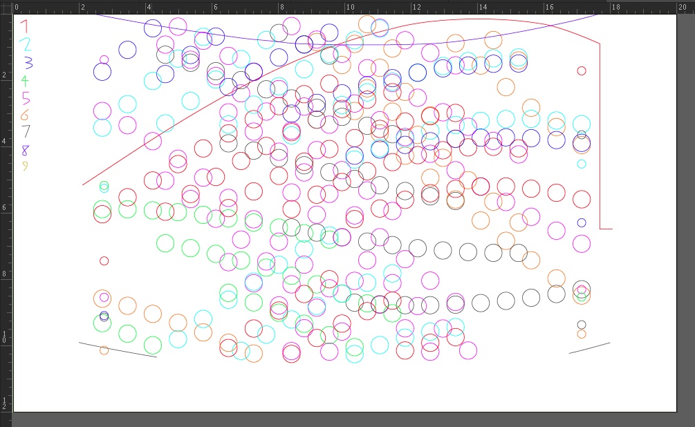
To prep the files for Glowforge, I had to recolor the cuts in the panels in 10” sections. Because the actual cut area is closer to 11”, any holes that were on the edge spilled over into the next section instead of being broken up. Each colored section was then aligned to the top and numbers were added as a reference. I didn’t know before cutting what order the layers would come in, but doing further research on the Glowforge Forum they are sorted by ascending hexadecimal values. See here: (https://community.glowforge.com/t/custom-inkscape-illustrator-coreldraw-and-affinity-designer-color-palettes-for-ordering-operations-in-gfui/7346)
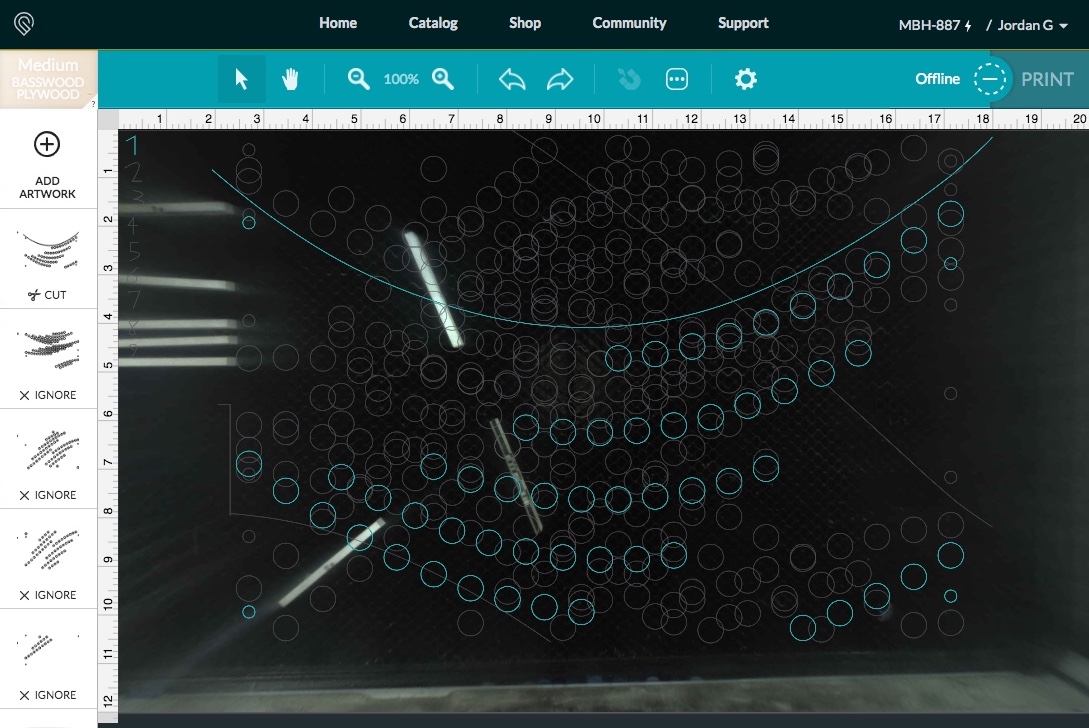
The process for cutting was to set all layers to Ignore but Cut 1, move the material through the Glowforge, then Ignore 1 and Cut 2, and repeat!
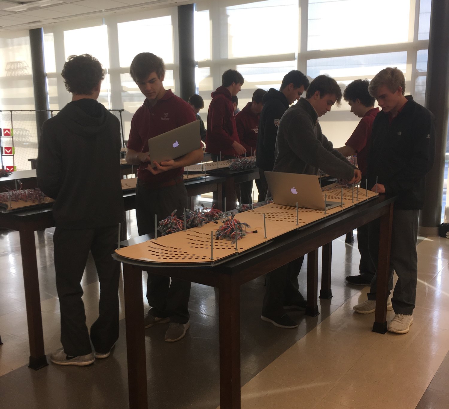
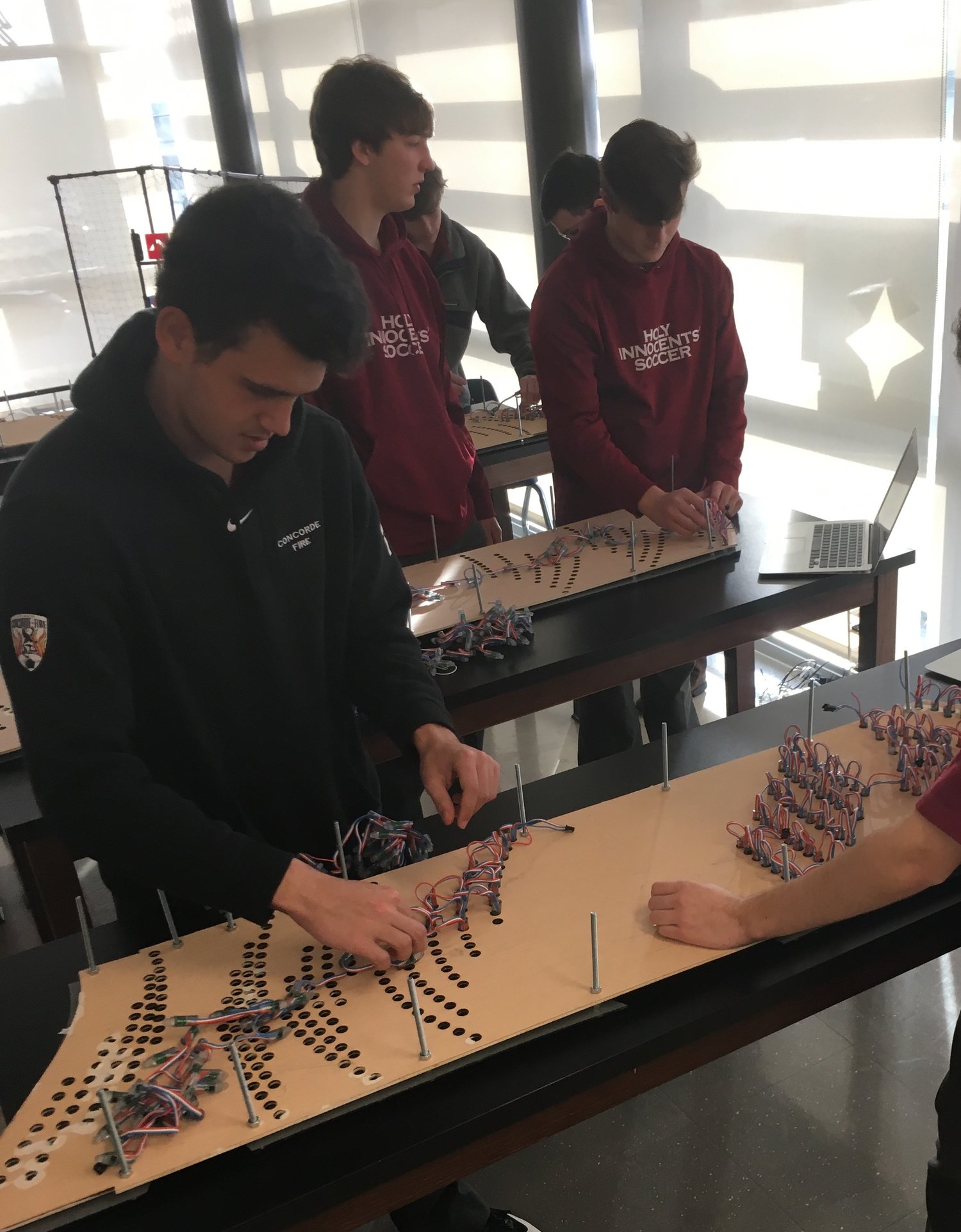
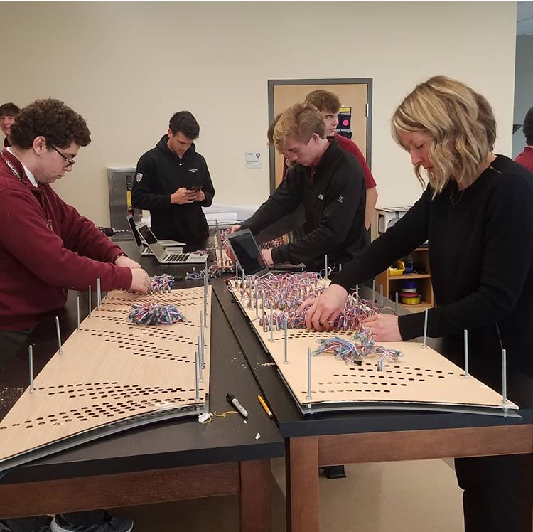
Mapping and Wiring
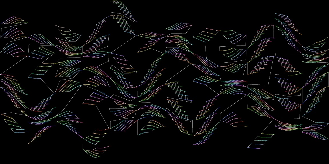
Similar to how I exported an image to convert to vectors in Illustrator, I exported another version of the layout that instead of drawing ellipses, the index of “led” was drawn in it’s place. I then drew on top of this image to determine the path that the LED strip should follow.
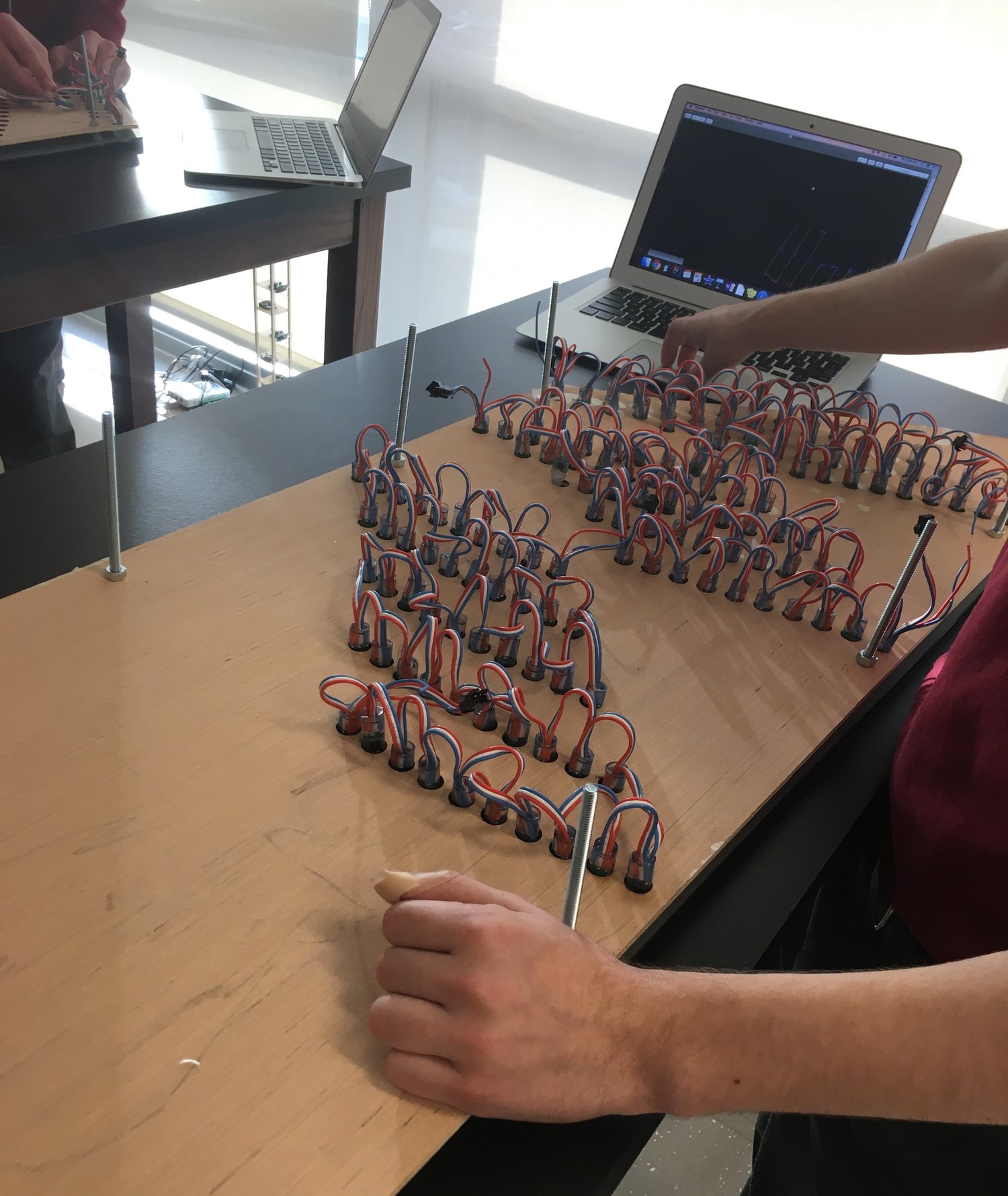
2 Teensys x 8 LED strips x 400 LEDs per strip, Processing and the Teensys think we are sending data to 6400 LEDs, but we are only using 4500. We need to remap the LEDs because we are skipping some and they are not being wired in the order they were drawn in Processing.
Using the wiring map above, I created a table to find the new index of each LEDs, adding the index of each strip and the position of the LED in each strip. I downloaded the table and used it in Processing to set the position of LED[] to the positions where each ellipse in the design was drawn (xpos[],ypos[]). Later in the code, the pixel color at LED[]’s x and y position is what is sent to the Teensys.
To send the data to the LEDs we used two Teensy 3.2 microcontrollers. The OctoWS2811 Library divides the pixel data and sends it to eight pins on the board. To make things easier, I decided to just have one pin per panel, so 12 pins would be used and there would be 4 left unused. Each panel has 350 or 400 LEDs, so I just made the LEDs per strip value 400 for all. It does not matter if the amount of data being sent is longer than the strip of LEDs.
Framing and Mounting
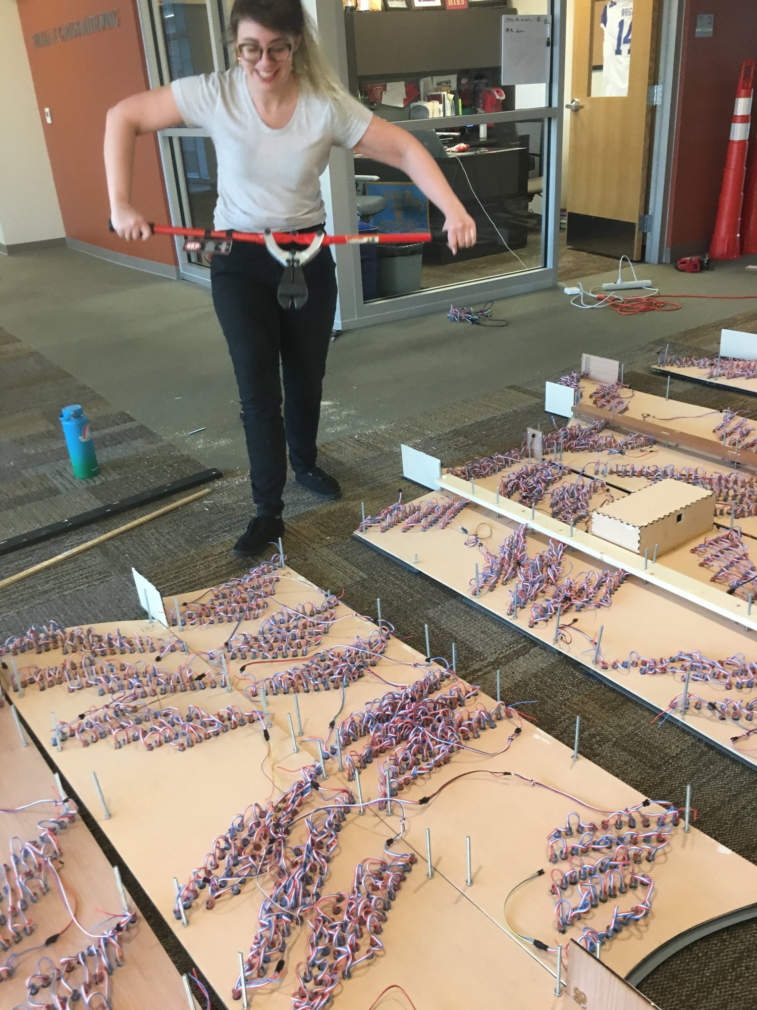
This step was challenging and resulted in a lot of revisions. The original plan was to cover the back with a second layer of plywood, vertical 1x3s would connect each panel, and a french cleat made from 2x4s would be attached horizontally to the 1x3s and on the wall. It would be all connected as one piece.
Because of the limitations of the Glowforge laser cutter, the alignment of our mirror acrylic and plywood pieces were slightly off, resulting in our material being bowed and bolts not going through straight, making it extremely difficult to get the plywood and 1x3s through the bolt holes. We ended up deciding to just mount panels in pairs, with the 1x3 running completely down the middle. and the side 1x3s just in the top section to support the 2x4 french cleat. Many unruly bolts were cut in the process.
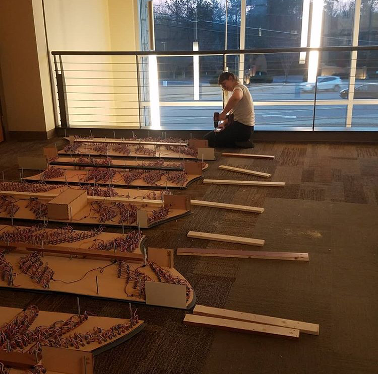
These changes were so helpful later on because there were wiring issues that needed to be fixed while the work was on the wall which the additional plywood would have prevented access. There was also room to reach behind panels. The french cleat system allowed us to easy hang 5 of the pieces with space in between, slide the pieces together when they were finished, and hang the 6th piece at the end.